
Technical Articles
MS3116 vs MS3476: Series, Termination and Mating Checks
2026-10-25T12:45:00.000Z
Compare MS3116 and MS3476 references without confusing Series I solder, PT-SE crimp and Series II rear-release configurations. Review the complete assembly.
MS3116 and MS3476 should not be treated as the same purchase line. MS3116 is associated with the MIL-DTL-26482 Series I solder-contact straight-plug references discussed here; MS3476 belongs to the Series II straight-plug references. The contact installation and rear configuration need their own review even when the front of two samples looks familiar. [1, 2]
This matters when a buyer is offered a “crimp replacement” for a soldered assembly. The decision covers the complete harness and the actual proposed mating pair, not just the connector body.
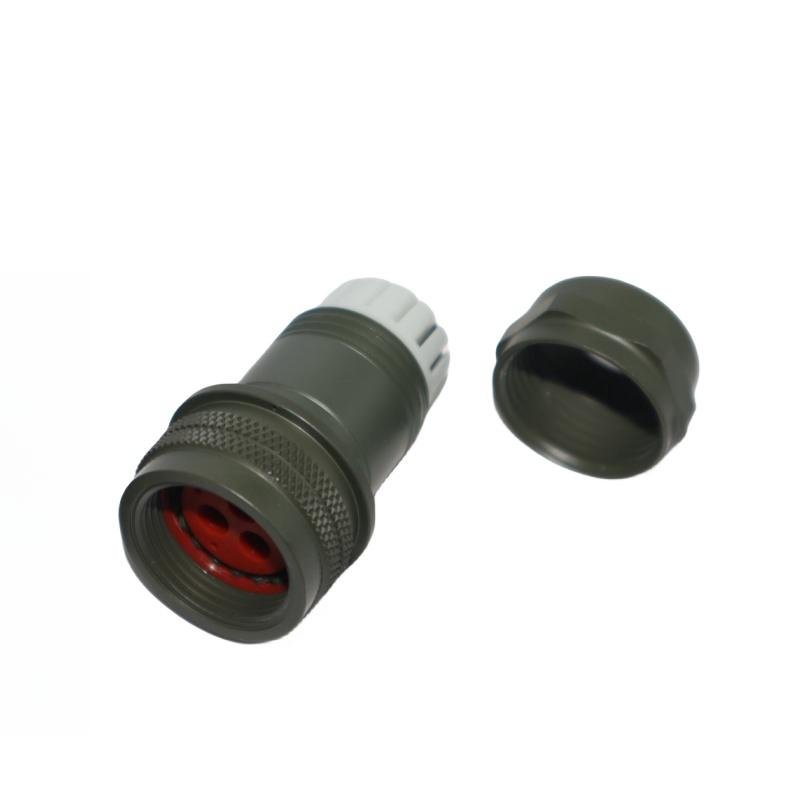
Figure 1. A bayonet cable-side supplier sample with rear hardware shown separately. Its full designation and termination requirements must be read from the applicable product record.
Separate the military reference from a broad family description
The PT catalog also contains PT-SE crimp-contact products within Series I. Consequently, the statement “Series I means solder and Series II means crimp” is too broad. Start with the complete reference and the relevant product section, not an abbreviated explanation of the standard. [1]
The cited Series II description identifies rear-insertable, rear-releasable crimp contacts. That affects the contact and tooling information needed for the proposed assembly. It does not establish that a contact from one assembly can be transferred to another. [2]
| Review item | Why it needs an explicit answer |
|---|---|
| Complete original and proposed references | Identifies the actual class, shell/insert, contacts and rotation |
| Mating-half reference and drawing | Supports the interface review independently of the termination discussion |
| Contact part number | Identifies the contact system being purchased |
| Wire and insulation dimensions | Establishes the termination and sealing inputs to verify |
| Applicable assembly instructions | Identifies the approved process and required equipment |
| Rear accessories and included parts | Prevents an incomplete substitution or quotation |
| Equipment-owner acceptance | Records whether the proposed change is permitted for this installation |
What changes when the contact system changes?
Prepare a fresh assembly BOM rather than carrying over a list of rear components by appearance. Identify the actual contact, any required sealing items, rear hardware and protection. Have the responsible team verify the assembly instructions and tooling for that combination.
Do not choose a crimp tool setting from a generic family comparison. The setting, inspection and acceptance requirements belong to the identified contact, wire, tool system and applicable instructions. This article supplies no universal crimp parameters or soldering recipe.
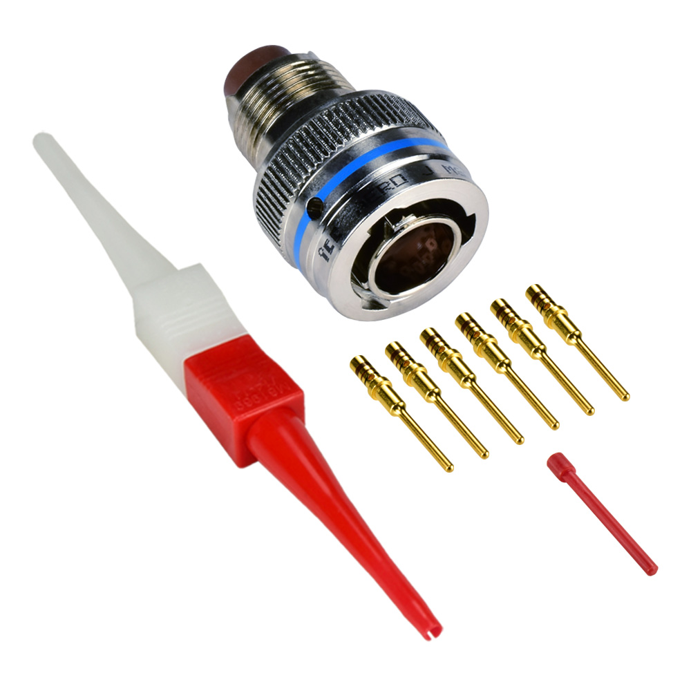
Figure 2. Original supplier photograph showing a removable-contact configuration, loose contacts and tools. This is a useful distinction from a solder-style assembly; it does not establish drop-in interchangeability.
Mechanical mating and replacement approval are different records
A family-level catalog statement may help identify which combinations deserve further checking. The proposed complete plug and receptacle still need a documented interface review. Do not infer either unconditional interchangeability or unconditional incompatibility from the two abbreviated names alone.
Even where a particular interface is found acceptable, that finding does not settle the contact system, installation, environmental performance, supplied documents or permission to replace an item in controlled equipment.
For an existing harness, record the answer to four questions:
- What exactly is staying on the equipment?
- What exactly is changing on the cable side?
- Which drawings and assembly documents support the change?
- Who must accept it before a purchase or installation proceeds?
This keeps a sourcing discussion from being mistaken for a released engineering change.
Show both ends of the assembly
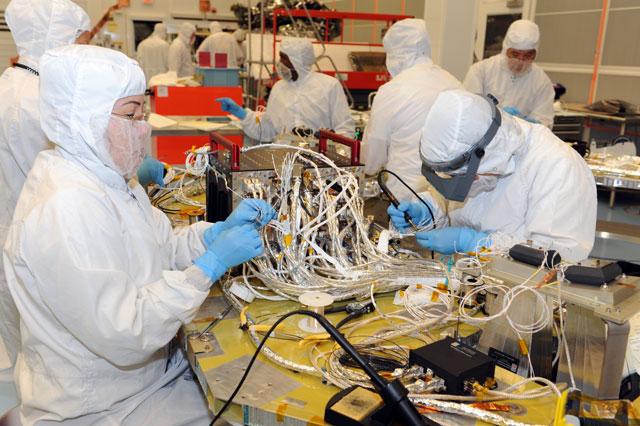
Figure 3. Electrical technicians building the connector harnessing for an MMS command-and-data-handling unit; NASA archive record published 8 December 2017. This is assembly context, not a comparison test of the pictured products. Credit: NASA/GSFC. Original archive. Context only; the connector series is not identified and this is not a Tradin installation or endorsement.
Request a mating-face view, side marking and rear view of the existing assembly. Show the cable and available installation space. If the proposed Series II configuration is not yet defined, leave its order code open until the relevant data is available.
The MS3116/PT06 guide addresses the narrower MS/PT nomenclature question. For this comparison, send the complete original and proposed BOM with the mating reference.
Tradin can review the sourcing requirement and its open configuration fields. Supply of a particular MS3476 item, documentation and suitability must be confirmed in the actual quotation; this comparison is not an inventory announcement.
Send the full references, quantity and assembly requirements →
References
[1] Amphenol PT Series catalog, 12-070-20, PT solder and PT-SE crimp sections; Series II reference note.
[2] Amphenol MIL-DTL-26482 Series II, rear-release crimp contact description and linked ordering/assembly information. Sources checked 18 October 2026.
FAQ
Does Series I always mean solder contacts?
No. The cited PT catalog also includes Series I PT-SE crimp products. Identify the complete reference and the relevant product section.
Does a similar front face make MS3476 a drop-in replacement?
No. Review the actual mating pair, contact system, rear components, assembly requirements and equipment-owner acceptance separately.
Is MS3476 stock promised by this article?
No. Supply of an exact item, its included components and documentation must be confirmed in the actual quotation.