
Technical Articles
MIL-DTL-26482 Insert Arrangements: Reading 8-3, 10-6 and 14-15
2026-10-21T12:42:00.000Z
Read PT/26482 shell and insert designations, contact populations and viewing conventions. Preserve the full configuration when requesting a quotation.
In a MIL-DTL-26482 insert designation such as 10-6, the shell-size reference and the insert-arrangement reference must be read together. The number after the dash identifies a layout; it is not a rule that can be extended to every circular connector family.
For the PT examples discussed here, look up 8-3, 10-6 and 14-15 in the applicable manufacturer's chart. Confirm the contact population and sizes, then check the complete connector reference, contact gender and polarization. [1]
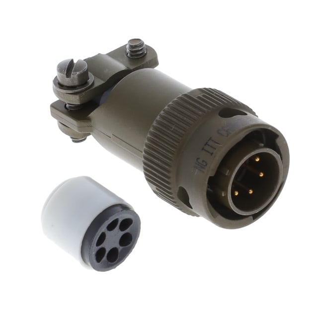
Figure 1. Supplier-source photograph from the Tradin reference collection. This is a form-factor illustration; it is not presented as a verified specimen of any of the three arrangements below.
Use a lookup record, not a naming shortcut
The PT catalog separates insert availability, arrangement patterns and alternate positioning. Those are different checks: a pattern's existence does not establish that every shell style and termination is available with it.
| PT layout reference | Shell reference | Population in the cited layout | What to verify next |
|---|---|---|---|
| 8-3 | 8 | Three contacts | Contact size, offered style and termination |
| 10-6 | 10 | Six contacts | Complete P/S and rotation designation |
| 14-15 | 14 | Fifteen contacts; review the mixed-size columns | Which circuit uses each contact size and the relevant wire requirements |
The table is a reading aid for these PT catalog examples. It is not a general pin-numbering convention, an availability statement or a circuit-to-cavity assignment. The actual arrangement drawing remains necessary.
Contact count does not finish the selection
Suppose a harness needs six circuits. “Six contacts” can help define an early requirement, but it does not establish the correct connector family, shell, contact system, mounting or keying. A six-contact candidate also needs to accommodate the actual circuits and the installation.
Keep three records separate:
- The connector arrangement: the specified shell/insert and permitted configuration.
- The circuit schedule: the function and requirements of each circuit, prepared by the responsible designer.
- The termination requirement: the identified contact and the actual conductor and insulation dimensions.
For a mixed-contact layout, do not allocate every circuit as if all cavities accepted the same contact. Ask for the cavity identification and contact specification on the drawing. This article deliberately does not assign currents or wire gauges from the arrangement number.
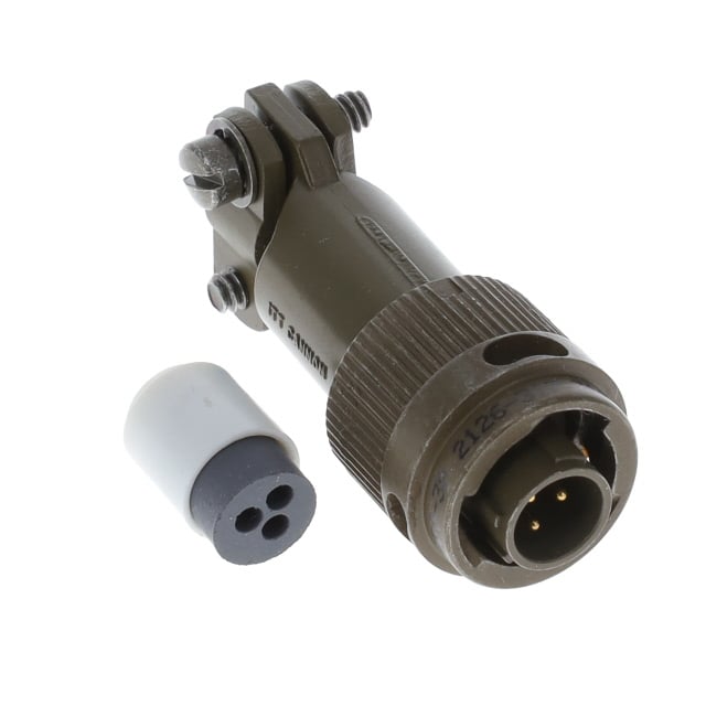
Figure 2. Original supplier photograph with three visible contacts and a separate rear grommet. The image illustrates identification inputs; the shell/arrangement and any circuit assignment still require the applicable chart.
Check which side of the drawing you are reading
An arrangement chart must state its viewing convention. Record that convention on the review sheet before comparing it with a photograph or a wiring document. Do not produce a wiring assignment by visually copying an unlabeled picture.
For an existing assembly, request one mating-face photograph and a separate view of the full marking. Where a rear view is useful, label it as a rear view. Keep reference features visible and ask the equipment owner for the controlled wiring document when circuit assignments are involved.
The MS3116/PT06 cross-reference guide explains why a service class or rear option cannot be dropped after a layout has been found.
Turn the lookup into a quotation request
Use this short input list when the arrangement is known:
| Input | Example of a useful answer |
|---|---|
| Existing complete reference | Copy the entire marking, not only “10-6” |
| Opposite half | Complete mating reference or its controlled drawing |
| Circuits and wires | Circuit count plus conductor/insulation requirements |
| Mechanical installation | Panel drawing or cable-exit space |
| Delivery scope | Connector, contacts and required rear accessories |
| Purchase conditions | Quantity, required date and document requirements |

Figure 3. NASA astronaut Michael Hopkins installing wire harnesses in Harmony, 24 November 2013. Installed routing is an additional review input alongside the contact-layout chart. Credit: NASA/Michael Hopkins. Original archive. Context only; the connector series is not identified and this is not a Tradin installation or endorsement.
If the arrangement is not known, say so. Send the marking, straight-on image, available drawing and circuit requirements for identification support. A quotation should retain the unresolved fields until they have been checked.
Browse the MIL-DTL-26482 connector range, or send the layout and complete requirement for quotation.
Reference
[1] Amphenol PT Series catalog, 12-070-20, printed pages 4–10: availability, alternate positioning and arrangement patterns. Recheck the exact offered configuration against its drawing. Source checked 18 October 2026.
FAQ
Does the arrangement suffix always equal the contact count?
Do not apply such a rule across connector families. Look up the shell/arrangement pair in the applicable catalog and verify the exact configuration.
Why does a mixed-contact layout need another check?
The circuit schedule must identify which contact size serves each circuit. The arrangement number does not establish the permitted wire or current for the assembly.
Which photograph helps identify an existing layout?
A straight-on mating-face photograph plus a readable side marking. Label any rear view separately and use the drawing for cavity and circuit assignments.