
Technical Articles
D38999 Keying and Polarization: Why Connectors May Not Mate
2026-10-22T12:44:00.000Z
Troubleshoot a D38999 mating inquiry using complete references, series, shell/insert, contacts, keying and correctly labelled interface photographs.
When a D38999 connector will not mate, stop treating the coupling as the first diagnostic tool. Similar shell dimensions and a familiar contact pattern do not establish that the two interfaces belong together. Identify both halves, their series and their specified keying before trying again.
This guide is a document-and-identification check, not a force, adjustment or repair procedure. Equipment handling and any subsequent mating operation belong under the applicable approved instructions.
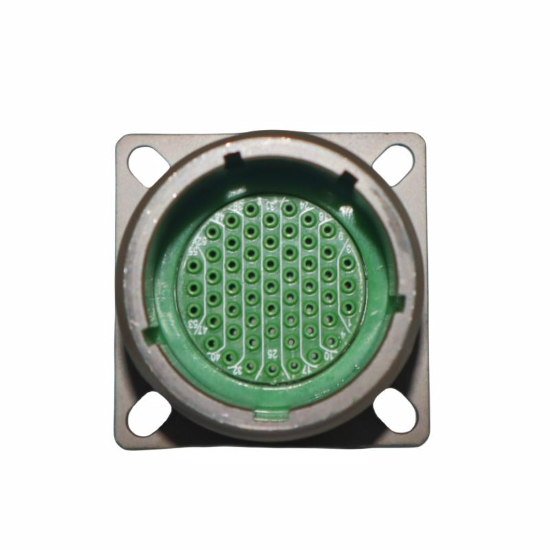
Figure 1. Front-facing supplier sample: preserve the shell reference and keyway orientation separately from the insert pattern. A photograph does not establish a keying angle.
Separate five questions that can look like one
“The connector is the same size” may refer to the outside diameter, the shell-size code, the visible contact count or the panel opening. They are different observations.
| Check | Record for each half | Reason to stop the review |
|---|---|---|
| Series and shell style | Complete marking and applicable drawing | The description says only “38999” |
| Shell and insert | Full shell-size and arrangement designation | Only a diameter or pin count is known |
| Contact system | Pin/socket and the specified contact configuration | Complementary electrical contacts are not established |
| Polarization | Normal or alternate keying code and its drawing | A suffix is missing or has been discarded |
| Physical condition | Clear views and an inspection record under the applicable procedure | Damage, contamination or an unexplained obstruction is suspected |
Manufacturer references distinguish the D38999 families and describe polarization features within particular series. Read the information for the actual connector; a keying table from a different family is not a substitute. [1, 2]
A photograph needs a declared viewing direction
Ask for a straight-on mating-face photograph of each connector. Keep a stable orientation, show the full shell opening and photograph the side marking separately. Record which face is being shown rather than labelling a picture simply “front.”
A view taken from the wire-entry side changes the relationship between the observer and the contact pattern. Rotating a photograph on screen can make an apparent mismatch look convincing in either direction. The comparison needs the manufacturer's stated view and reference features.
Do not infer a polarization angle from a perspective image. Even a sharp photo is an identification aid rather than a dimensional inspection. If the suffix or drawing is unavailable, that is an unresolved input—not permission to guess the nearest position.
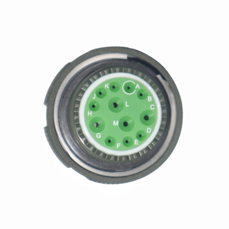
Figure 2. Rear seal and cavity lettering of a different supplier sample. Label this as a rear view; do not mirror it into a circuit assignment or assume the two photographs form a mating pair.
Make the mismatch report useful to the next person
Instead of forwarding “will not connect,” send a compact comparison record:
- Full part number on the installed half and full proposed mating reference.
- Manufacturer or offered-item identity where known, with drawing numbers and revisions.
- Mating-face and side photographs for both halves, labelled by connector and viewing direction.
- A short description of what was observed, without further forced mating attempts.
- The project's approved handling and replacement requirements.
The useful outcome is one of three states: the documented configuration supports further inspection, information is still missing, or the references show a mismatch. Keep the decision and its evidence together. A supplier's family-level cross-reference is not the same record as approval to fit a replacement.
NASA's published connector-handling standard is a useful reminder that handling instructions have a defined scope and do not replace approved engineering procedures. It is not evidence that a connector offered by Tradin meets NASA requirements. [3]
Consider the installation as well as the face
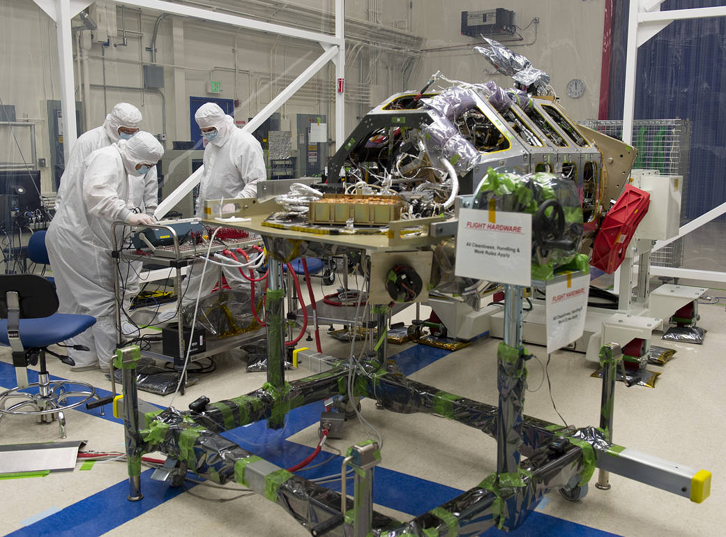
Figure 3. LADEE engineers checking an electrical interface before connection, 21 December 2012. Credit: NASA Ames/Eric James. Original archive. The check addresses pin location and safe connection; no D38999 connector is identified in this image and no Tradin work is claimed.
A cable pulling sideways, restricted access or a mounting problem can complicate an inspection. Show the surrounding equipment in the review package. Leave the actual diagnosis and corrective work to the responsible team using the applicable instructions.
For a known Series III plug, the D38999/26, /20 and /24 mating guide explains the separate mounting decision. The MIL-DTL-38999 category is the starting point for a sourcing inquiry.
Need the proposed pair checked before reordering? Send the two complete references, oriented photographs, quantity, installation drawing and any original-only or approval requirements.
Submit both connector references for review →
References
[1] Amphenol 38999 catalog, applicable series, ordering information and key/keyway drawings.
[2] Amphenol Connector Reference Guide, Volume 2, series distinctions.
[3] NASA GSFC: Flight Cable/Electrical Connector Mating and Demating, scope and precedence of approved engineering instructions. Sources checked 18 October 2026.
FAQ
Can I identify keying from an angled product photo?
Use a photograph for identification support, not a dimensional or keying-angle acceptance. Obtain the specified viewing direction and applicable drawing.
Does the same contact count prove a mating pair?
No. Series, shell/insert, contact system, polarization and other applicable requirements still need review.
What if the proposed halves will not connect?
Stop forced attempts and follow the applicable handling and inspection instructions. Send both full references and labelled photographs for a documented review.