
Technical Articles
How to Assemble an AS85049/M85049 Backshell on a MIL-DTL-38999 Connector
2026-09-03T02:00:00.000Z
AS85049 / M85049 ASSEMBLY GUIDE · DRAFT FOR PRE-REVIEW
AS85049 / M85049 ASSEMBLY GUIDE · DRAFT FOR PRE-REVIEW
A reliable backshell assembly starts before any hardware is tightened. The connector series, rear accessory interface, shell size, cable entry, shield strategy and strain-relief method must all be confirmed from the applicable drawings. This guide provides a controlled workflow without inventing universal torque or compatibility values.
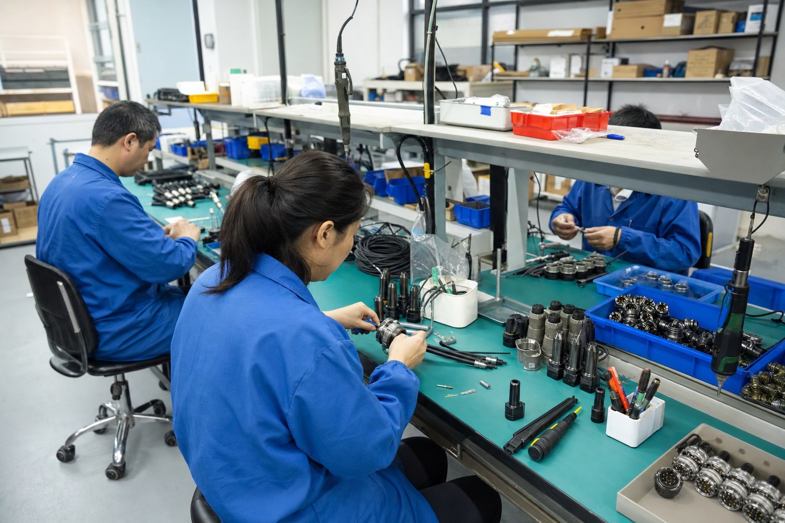
Representative connector-assembly workspace. It is not evidence of a specific M85049 configuration, qualification test or customer installation.
Can any M85049 backshell be installed on any D38999 connector?
No. M85049 is a large accessory family, not a universal fit statement. The selected slash sheet and connector designator must match the MIL-DTL-38999 series and rear accessory interface, while the backshell shell-size code, cable entry, material, finish, angle and locking option must match the actual assembly.
For example, M85049/51 and M85049/52 are 90-degree and straight strain-relief families associated in the cited catalog with specific connector designators. They must not be presented as generic D38999 backshells. For D38999 work, start from the applicable AS85049 slash sheet or manufacturer drawing that explicitly lists the target D38999 series.
Selection comes first: verify connector designator + shell size + cable entry + function before planning the assembly sequence.
Information required before assembly
Complete connector part number, including series, shell style, shell size, insert arrangement, contact type and keying.
Complete AS85049/M85049 or manufacturer backshell part number, including slash sheet, connector designator, shell size, material/finish, locking option and cable entry.
Applicable connector and backshell drawings, assembly procedure and any controlled workmanship instruction.
Cable construction: overall diameter, jacket material, conductor sizes, shield or braid construction, breakout geometry and minimum bend radius.
Rear termination objective: strain relief only, environmental sealing, overall shield termination, individual shield termination, potting or a molded-boot transition.
Inspection and documentation requirements, including any qualification, traceability or customer-specific acceptance records.
Controlled assembly workflow
1. Confirm the exact connector-to-backshell interface
Compare the connector rear accessory interface with the backshell drawing. Confirm the connector designator and shell-size mapping; do not select only by the visible connector diameter. Check that the coupling nut, thread form or engagement method, angular envelope and key clearance are correct for the connector series.
2. Confirm the backshell-to-cable interface
The cable-entry range must fit the finished bundle after braid, sleeving, tubing or jacket layers are considered. A cable that is too small may not receive effective strain relief; a bundle that is too large may be damaged or may prevent the clamp, boot or sealing element from seating correctly.
3. Put every rear component on the cable in the correct order
Before terminating contacts, stage the coupling nut, backshell body, shield hardware, clamp parts, boot, adhesive or other rear accessories in the order shown by the approved assembly drawing. This avoids destructive rework after contacts are installed. Protect sealing surfaces and threads from contamination.
4. Terminate and inspect the connector contacts
Complete contact termination and insertion under the applicable connector instructions. Verify contact type, wire range, crimp or solder process, cavity location, insertion depth and rear-grommet condition. The backshell should not be used to hide an unresolved contact or wire-routing problem.
5. Dry-fit the backshell without loading the wires
Bring the backshell forward squarely and confirm free engagement. Wires should enter without twisting, pinching or pulling against the rear seal. If engagement is not smooth, stop and inspect the part-number match, thread condition, wire dress and component order rather than forcing the coupling.
6. Complete shield termination only by the approved method
Banding, crimp-ring, cone, spring and Tinel-Lock-style terminations use different preparation, tooling and inspection rules. Follow the selected backshell procedure for braid trim length, overlap, landing-area cleanliness, tool setup and acceptance. A generic instruction cannot replace the slash-sheet or manufacturer assembly procedure.
7. Set strain relief and exit direction
Dress the bundle so the clamp or relief supports the cable without flattening insulation, creating a sharp bend or transmitting load to the contacts. For angled backshells, confirm final orientation and service clearance before tightening the relief hardware. Use only the torque and locking method stated by the applicable drawing or controlled work instruction.
8. Install the molded boot or environmental transition when specified
Match the boot lip and recovered dimensions to the backshell adapter and cable. Confirm adhesive compatibility, surface preparation, recovery temperature and heat-sensitive components before applying heat. A boot can contribute sealing and strain relief, but it does not correct a mismatched backshell or an unsupported cable bundle.
9. Perform final inspection
Backshell coupling is fully seated and secured by the specified locking method.
No wire, insulation, braid or sealing element is trapped in the coupling interface.
Cable exit and bend radius match the installation envelope.
Shield termination and strain relief pass the project-specific visual and mechanical checks.
Boot or sealing transition is fully recovered and bonded where specified, with no scorching, voids or exposed adhesive paths.
Part numbers, tools, inspection results and deviations are recorded for traceability.
Common causes of backshell assembly failure
Treating M85049 as one interchangeable family instead of verifying the slash sheet and connector designator.
Matching the connector shell size but ignoring cable-entry range and finished bundle diameter.
Applying a remembered torque value from another backshell or connector family.
Cutting shield braid before the exact termination method and trim length are confirmed.
Using the backshell clamp to force an immediate bend that loads the rear seal or contacts.
Heating a boot without confirming material, adhesive and nearby component limits.
Frequently asked questions
What torque should be used for an M85049 backshell?
Use the torque and tool specified by the applicable slash sheet, product drawing or controlled assembly instruction. There is no safe universal value for every M85049 configuration, material, shell size and locking design.
Can the backshell be selected from connector shell size alone?
No. Shell size is one input. The connector designator, rear interface, function, angle, cable-entry range, material/finish, shield method and locking option also affect selection.
Does adding a heat-shrink boot make the assembly environmental?
Not automatically. Environmental performance depends on the complete connector, backshell or adapter, boot, adhesive, cable jacket, installation process and validation. Use only documented combinations and acceptance criteria.
Related Tradin Connect resources
MIL-DTL-38999 series overview: https://tradintech.com/mil-spec-connectors/mil-dtl-38999
Connector accessories: https://tradintech.com/connector-accessories
M85049/52 straight strain relief: https://tradintech.com/products/m85049-52-straight-strain-relief-backshell
M85049/51 90-degree strain relief: https://tradintech.com/products/m85049-51-90-degree-strain-relief-backshell
Request a configuration review: https://tradintech.com/request-a-quote
Sources used for this draft
Use the current product drawing, applicable specification and approved internal engineering documents for final design decisions. These public sources support the editorial draft:
Glenair - How to Select the Proper Backshell: https://www.glenair.com/backshells/how-to-select-the-proper-backshell.htm
Glenair - AS85049 qualified backshells and connector accessories: https://www.glenair.com/mil-spec/as85049-qualified-backshells-and-connector-accessories/
Glenair - Mil-Spec part-number cross-reference table: https://www.glenair.com/mil-spec/mil-spec-part-number-cross-reference-table.htm
TE Connectivity - Circular connector backshells: https://www.te.com/en/products/connectors/connector-accessories/connector-backshells/intersection/circular-backshells.html
TE Connectivity - Standard MIL-DTL-38999 connectors: https://www.te.com/en/products/connectors/circular-connectors/intersection/d38999-connectors-special-designs.html
Request a configuration review
Send the complete connector or backshell part number, drawing, photo, cable details, quantity and BOM to Tradin Connect for matching and quotation. State whether you require an original item, a compatible option for validation, or a drawing-based custom solution.